

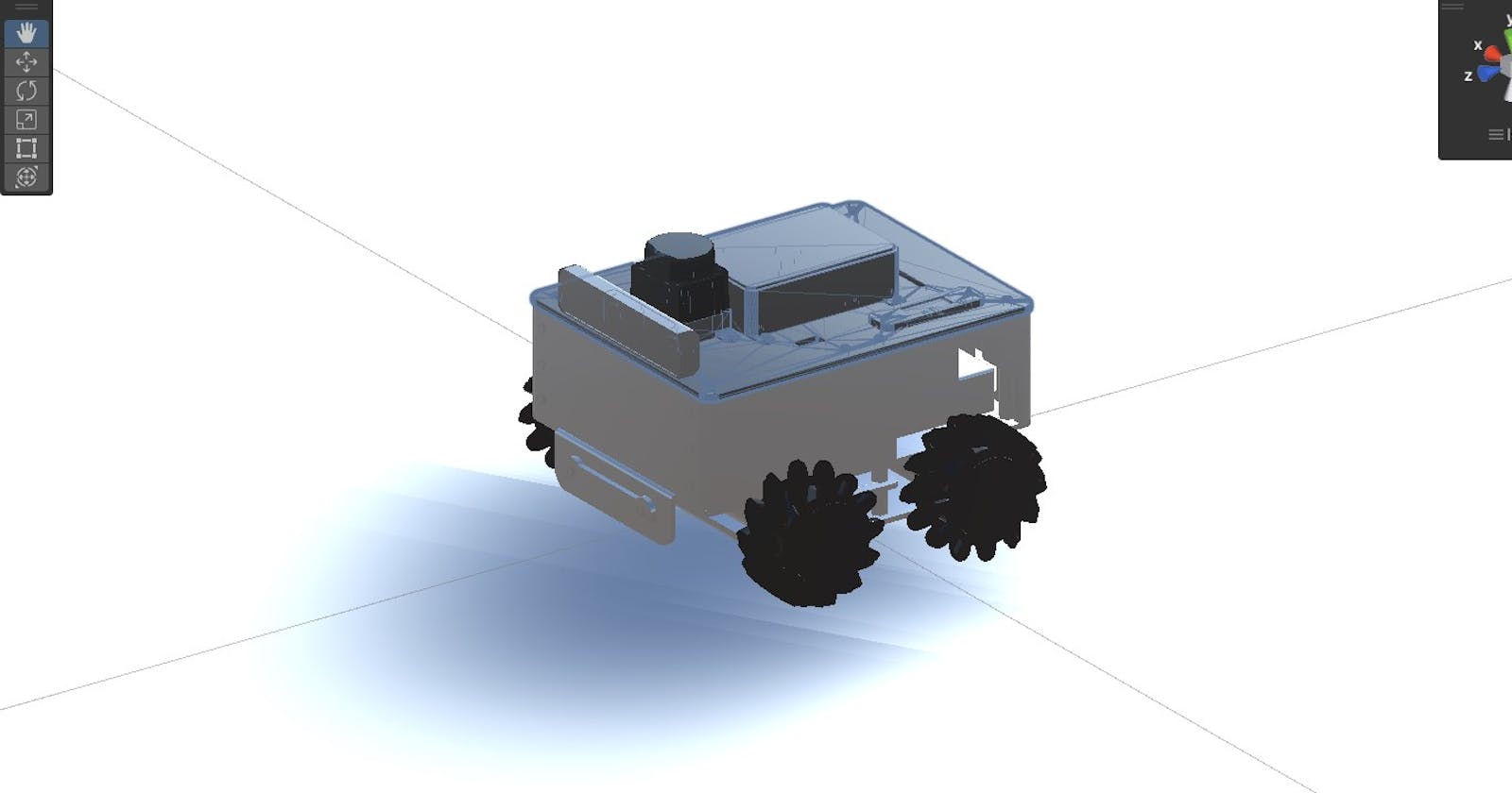


Over the last few weekends, I've been trying to set up a visualization for AKROS2 on Unity. I have had some successes, and I think I have reached a state where I have correct transforms, and can visualize most of the topics quite correctly. In this post, I will talk about how I did all of it in Unity 2022.2.13 (please be warned that it might not work in previous versions of Unity, it does not work in the 2020 and 2021 versions for example).
Setting Up
First, setting up the Unity environment. There are a few packages that need to be installed on Unity:
TCP Connector: This package enables the connection to a remote robot running ROS 2 (which is on the same Wi-Fi network as the computer running Unity). This can be installed on Unity using the steps provided here.URDF Importer: This package enables the import of a URDF file into Unity. The importer also corrects the frames of reference from the Z-up orientation in ROS 2 to the Y-up orientation in Unity. This package can be installed using the steps provided here.Unity Robotics Visualization: This package enables the visualization of ROS / ROS 2 topics in Unity. It can be installed using the steps provided here.
Finally, the last package ROS_TCP_Endpoint needs to be cloned in a ROS workspace and built like any other ROS package. Make sure the correct branch is cloned and built, as there are different ROS and ROS 2 branches. This package establishes the connection with the TCP Connector package on Unity.
With these packages installed, a new project can be created for the AKROS2 visualization.
Importing the URDF
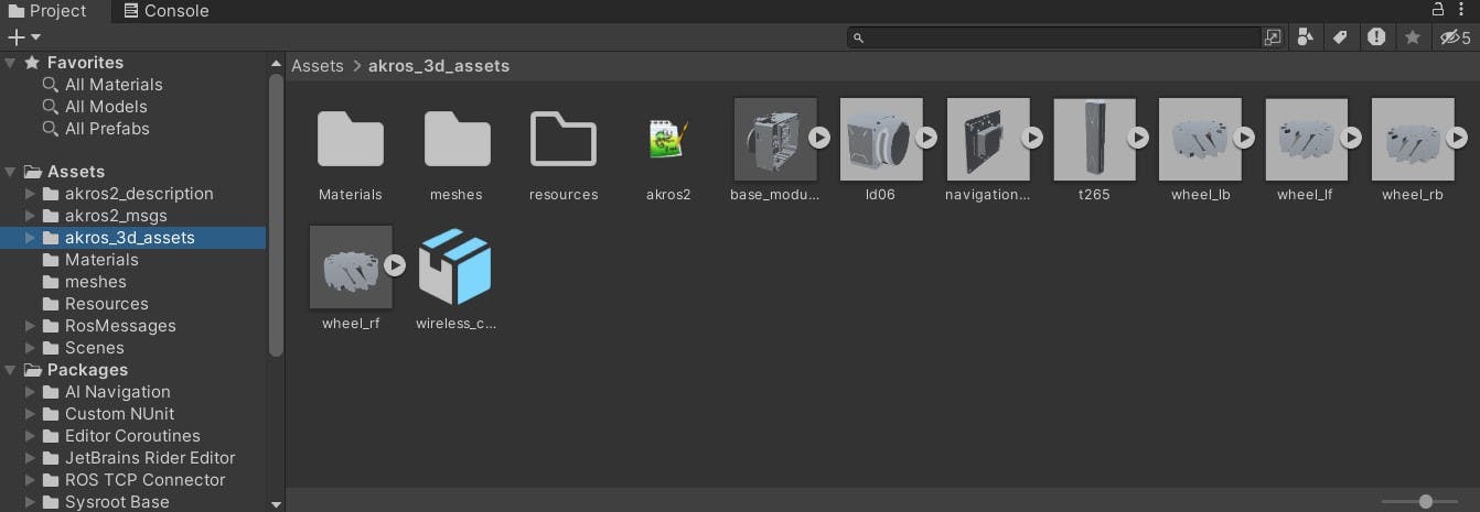
After setting up and creating a new project, it is time to import the URDF. First, the URDF and the associated meshes need to be added to the project in the Assets directory. This can be easily added by simply cloning the akros_3d_assets repository into the assets. Make sure to clone the akros2_urdf branch, since that's the only one that has a URDF. This URDF was generated using the Xacro files in the akros2_description package.
Next, the URDF can be imported by navigating to it from the Project window and selecting the Import Robot from Selected URDF File option upon right-clicking on the URDF file (akros2 in the following image).
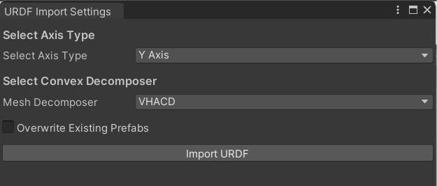
Please use the setting shown in the following image when importing the URDF:
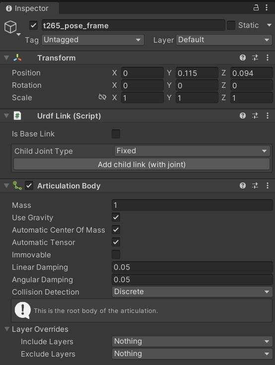
A few things can be observed - in our Xacro and corresponding URDF files, the t265_pose_frame is the root frame, instead of base_link (this was necessary to make the T265 camera work properly), and the origin of the world seems to be connected to the root frame. So, a few things need to be changed.
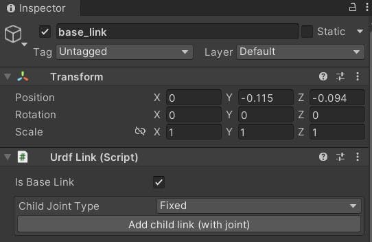
First, an articulation body component is added to the t265_pose_frame. This is done because of the Unity Nav2 SLAM example, where the root frame of the robot is also an articulated body. It seems to work without issues for now.
Next, base_link needs to be set as the root frame. This can be done by unselecting the Is Base Link option for the t265_pose_frame and selecting the same option for the base_link.
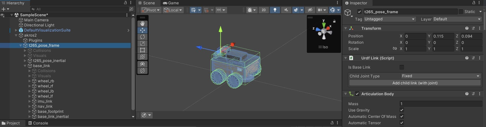
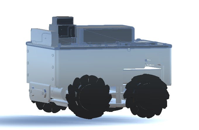
Finally, it can be seen that the t265_pose_frame is still situated at the origin, so the tree needs to be translated such that the origin is situated at the base_link frame.
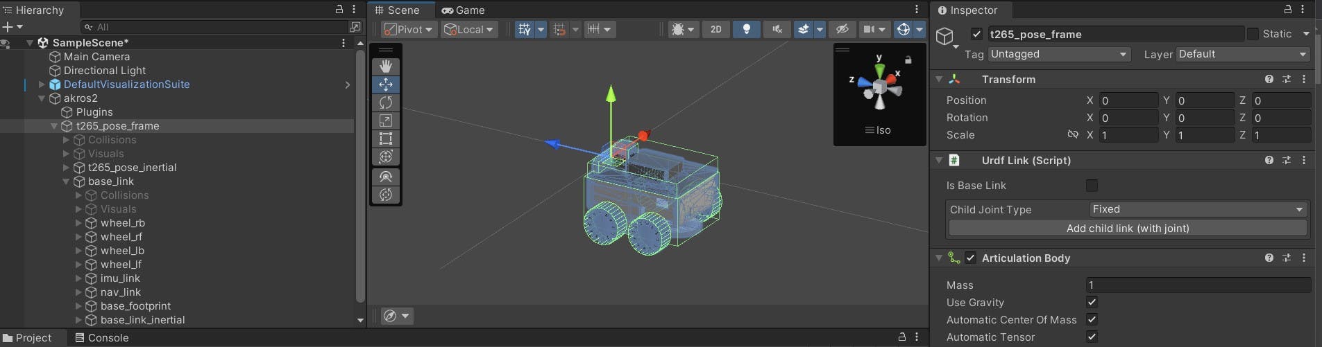
In this case, it can be done by setting the t265_pose_frame translation to y:+0.115, z: 0.094.
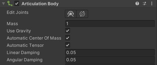
Next, before continuing make sure that gravity is enabled for each frame and articulation body. Other settings are configured automatically by the URDF importer.
This brings us to the next issue - in the current state, with gravity enabled and the play button pressed, the robot drops down (and does not stop). This is because there is no plane underneath the robot. So, the final thing to do is add a plane and configure the transform so that it is below the robot.
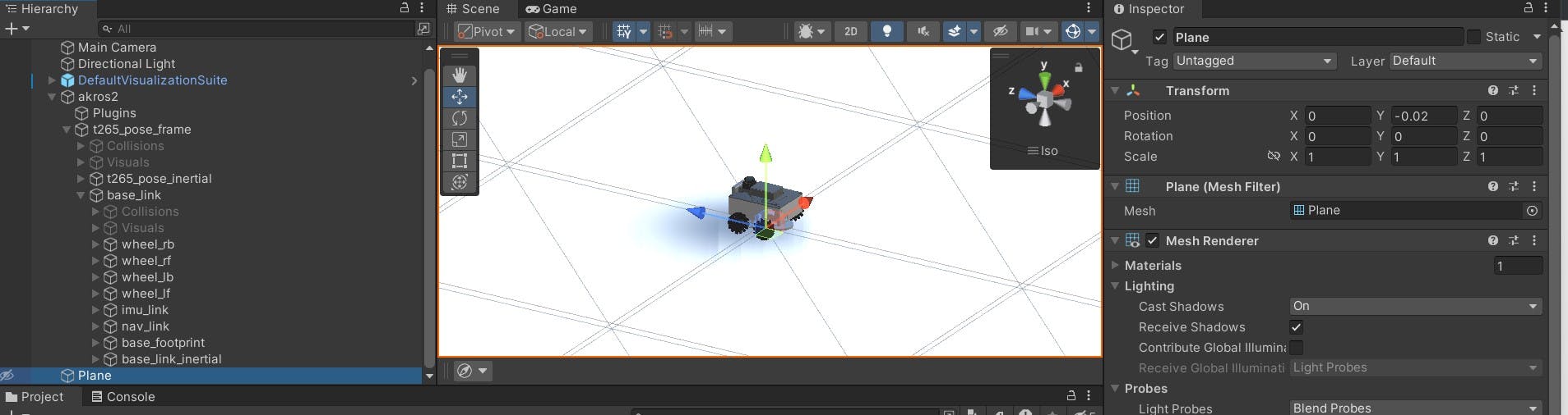
In my case, the robot is levitating a few millimeters above the plane, which is okay as the robot drops onto the plane when the play button is pressed.
Visualizing topics in Unity
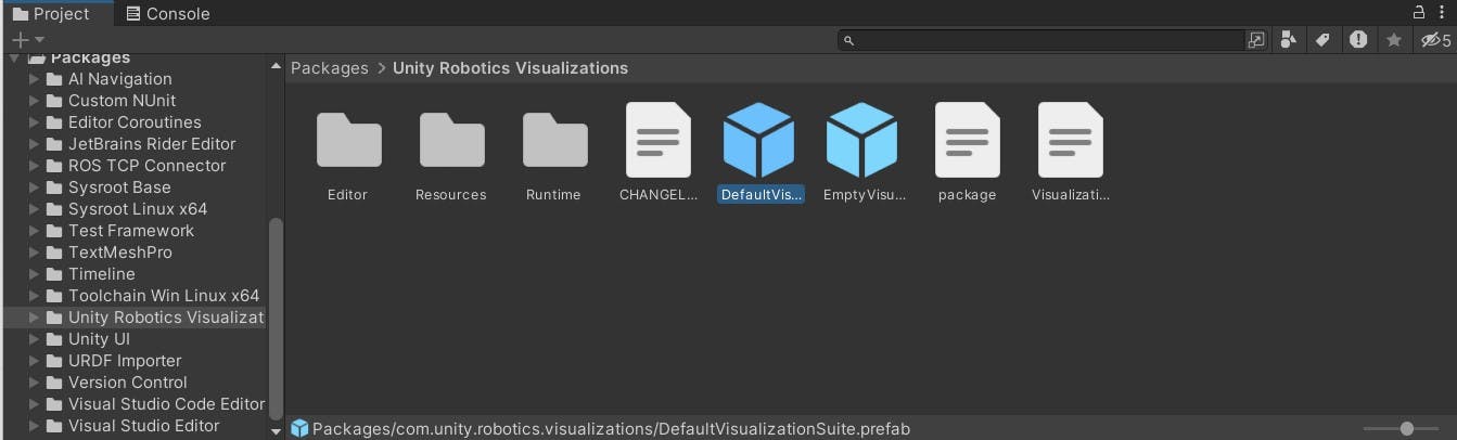
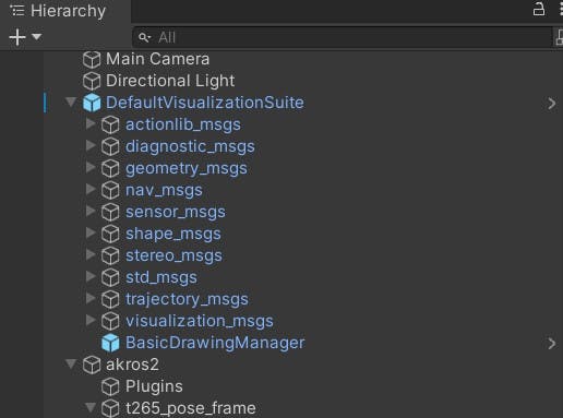
First, to set up a visualization of topics, the DefaultVisualizationSuite needs to be added as an object in our scene. This can be done by navigating to the Unity Robotics Visualization directory under Packages in the Project window. From there, the DefaultVisualizationSuite prefab can be dragged into the scene.
This package includes a list of topics and message types that can be visualized in Unity. These visualizations can be configured by selecting the specific message type under the DefaultVisualizationSuite prefab and configuring options like topic name, and frame ID to name a few.
I first configured the following topics:
geometry_msgs/Twist: Configured the script with the topic name and frame ID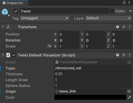
nav_msgs/Odometry: Configured the script with wheel odometry and tf topic names. This is only the wheel encoder odometry published by the micro-ROS node. The actualodom->base_linktransform is provided by the T265 cam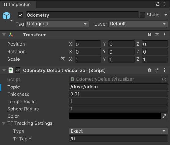
sensor_msgs/Imu: Configured the script with IMU and tf topic names.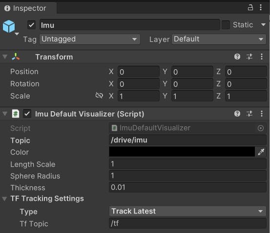
sensor_msgs/LaserScan: Configured the script with the laser scan and tf topic names. The visualization script does not allowInforNaNvalues, which my laser scan topic does publish, so I had to filter the laser scan topic using laser scan chain filter plugins:LaserScanRangeFilterwhich limits the range of the scan between thresholds and anything outside the range is set toNaN, and then theInterpolationFilterthat sets any (invalid)NaNvalues to a valid interpolation of neighboring valid values. The visualization script is configured with the filtered laser scan topic name.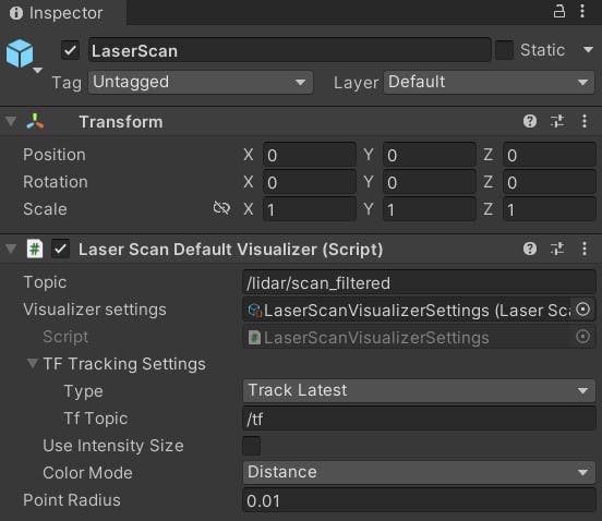
Finally, it was time to run the visualization. I started off by launching the robot, and in a separate terminal, launching the TCP endpoint script:
$ ros2 launch ros_tcp_endpoint endpoint.py
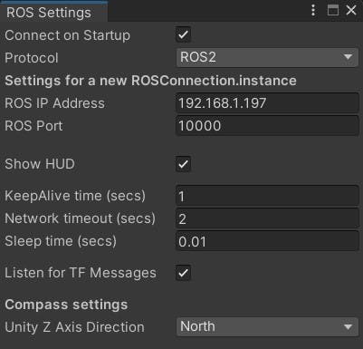
On Unity, I went to Robotics > ROS Settings and configured the IP address of the robot and the port number of the TCP endpoint.
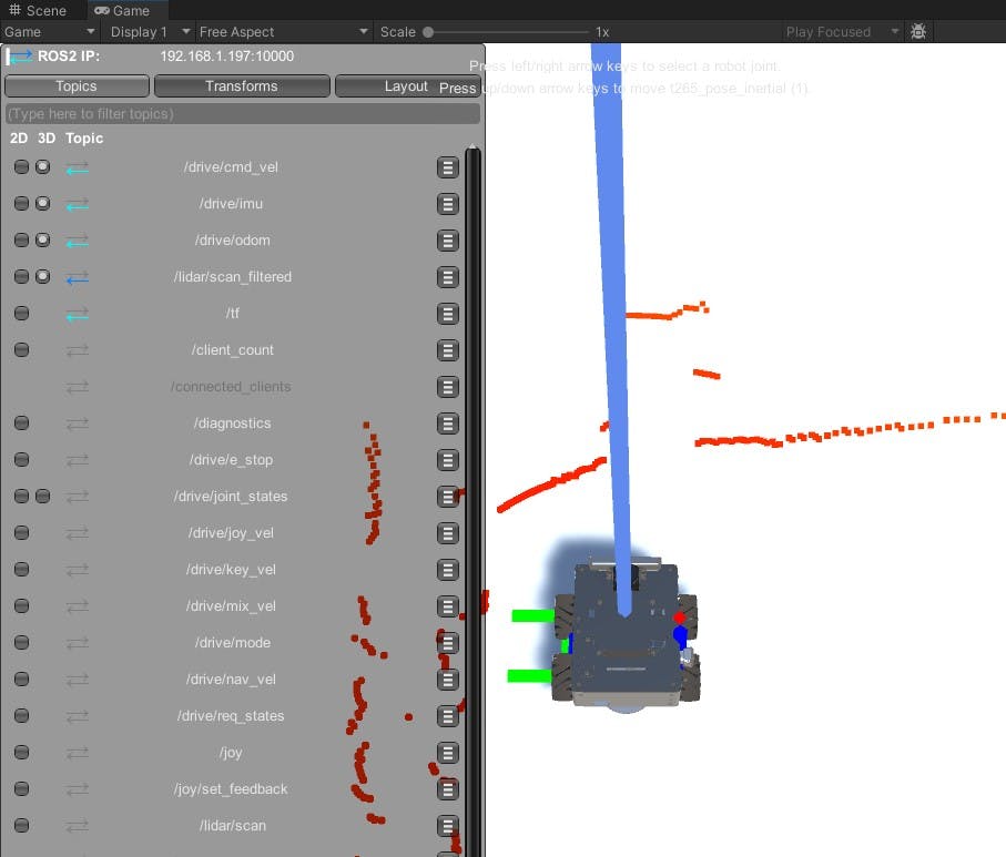
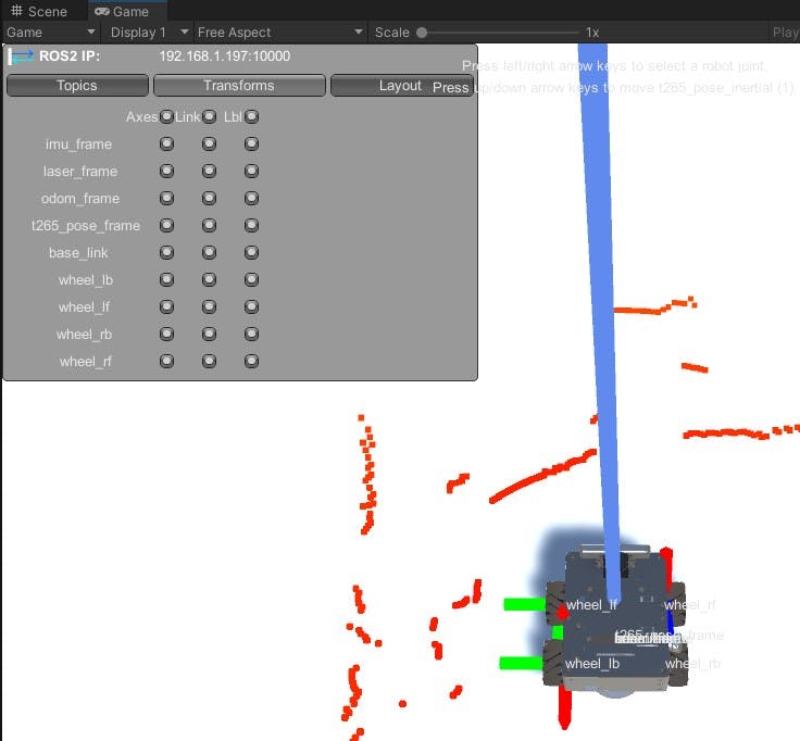
Next, I connected to the TCP endpoint by pressing the play button. A Heads-up Display (HUD) is shown in the Game view, from where you can choose the topics and transforms to show:
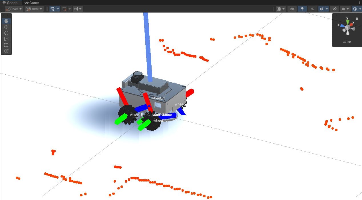
A better visualization can be seen in the Scene view, where you can change camera angles and zoom in or out.
Challenges
While most of the visualization seems to work, I observed a few issues:
Fixed frames: The
base_linkframe is fixed to the plane and I can observeodom_frame(T265 odometry frame) andenc_odom_frame(wheel encoder odometry frame) moving around when I move the robot. For now, I am usingodom_frameas the main odometry frame, and I would like it to be fixed to the plane so that I can see the robot moving.Twist rotation: When the robot is rotated in a particular direction, the twist visualization shows the opposite direction of rotation. When translating the robot, the visualization is correct. I am not sure what is happening here.
JointState messages: I also tried visualizing the joint states (position and velocity) for each motor. However, the motors rotate around a different axis altogether, have a look:
Next Up:
I will get some help from a colleague at work (who knows Unity) to at least try and fix the issues there. Hopefully, this can be a starting point for a similar project at work. I meanwhile want to move on to using Gazebo instead. I want to try and set it up on WSL2 on my laptop. I want to set up ros2_control on Gazebo, so this should help in the efforts.
I was also able to install ROS 2 and micro-ROS on my Raspberry Pi Zero 2 W. I have also ordered Pimoroni's new Inventor Hat Mini, and I plan on using it to experiment with ros2_control and its differential drive controller. Once I am comfortable working with ros2_control, my next goal would be to write a mecanum drive controller and hardware interfaces for the AKROS2 robot.
I also spent some time during the long weekend playing with the Wio Terminal and trying to get it working with micro-ROS over WiFi. I tried all kinds of different things over a few days but nothing worked - I was unable to connect to my access point. However, I was able to get it working with micro-ROS over serial.